Infelizmente, este documento não está disponível em português. Abaixo está a versão em inglês.
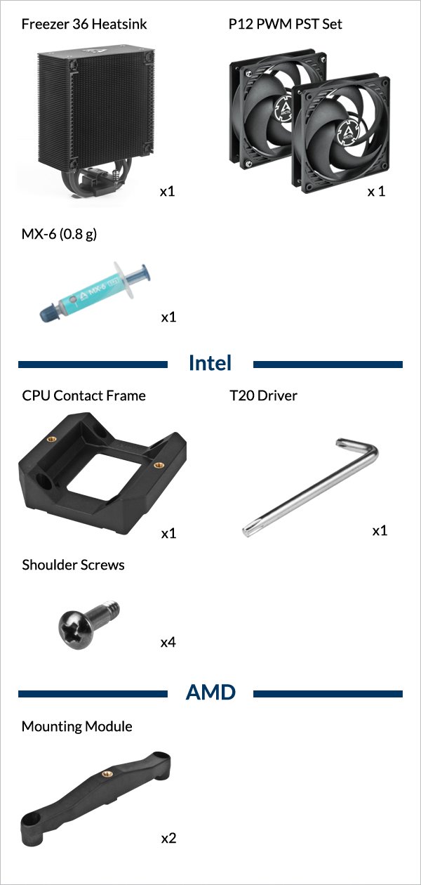
- AMD – AM5, AM4
- Intel – LGA1851, LGA1700
Select your CPU Socket
Required Tools

Warning
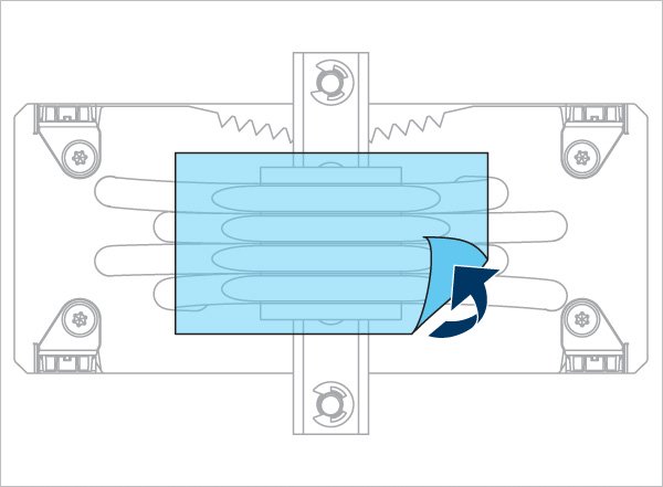
Keep the removed screws for later installation of the mounting modules.
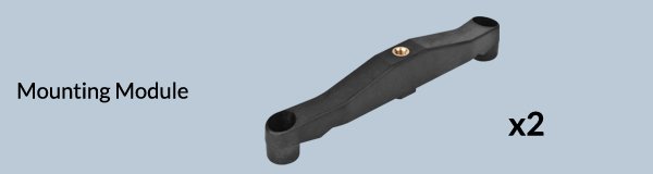
The screws loosened when removing the AMD mounting are now needed to install the modules.
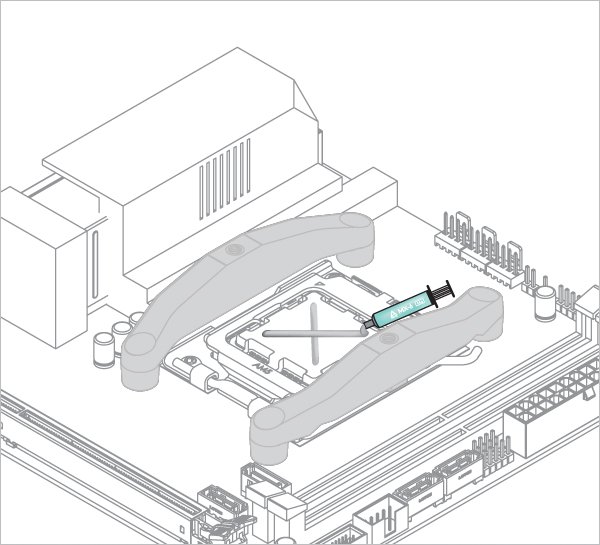

Refer here to learn more about how to apply thermal pastes.

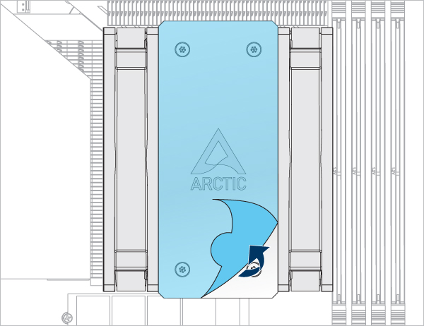
- Back Exhaust
- Back Intake
Select airflow direction
The fans can be rotated to aid cable management

The fans can be rotated to aid cable management
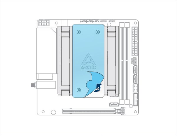
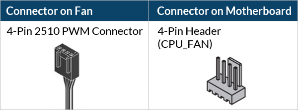
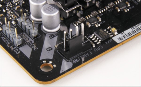
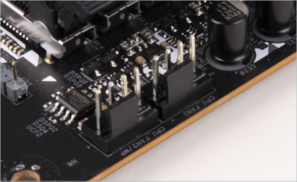
- CPU_FAN
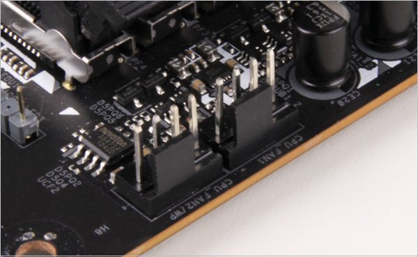
- CPU_FAN + CPU_OPT
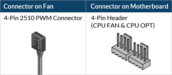
Select your CPU fan header configuration
To get the best out of your cooler, it is recommended to adjust the fan speed control in the BIOS, follow this guide to adjust your PWM.
To get the best out of your cooler, it is recommended to adjust the fan speed control in the BIOS, follow this guide to adjust your PWM.
Required Tools
 T20 Screwdriver (Included in packaging)
Attention
Secure the socket backplate in one of the 2 ways shown below depending on the status of your motherboard.
To support the socket backplate, place it on a flat, horizontal surface, like a thick padding (e.g., the packaging inner card)

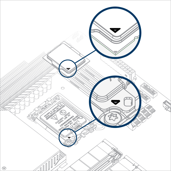
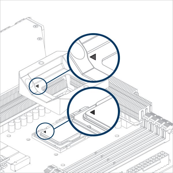
Open the Independent Loading Mechanism (ILM), align and place the CPU into the socket
Attention
Keep the removed parts for reassembly in the future. The ILM must be reinstalled if the motherboard is to be returned for service or warranty.


Attention
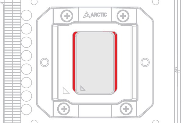
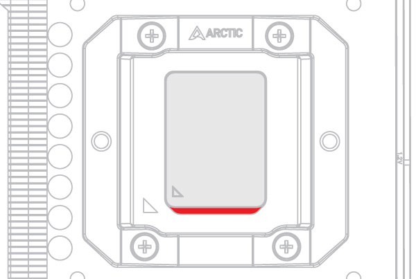
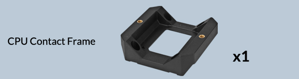
The CPU Contact Frame is made to be compatible with both LGA1851 and LGA1700 CPUs, select below to see your CPU fitment.
Warning
Loosely engage all 4 screws by 2 turns before tightening them in a cross pattern evenly to avoid damaging the CPU.

The thick padding can be removed after the CPU Contact Frame is tightened.
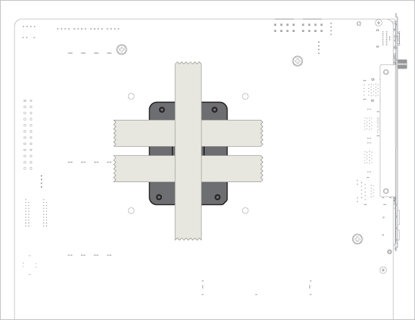
Apply painter’s tape on the backside of the motherboard to secure the socket backplate. Lay the PC case flat on a horizontal surface.
Open the Independent Loading Mechanism (ILM), align and place the CPU into the socket
Attention
Keep the removed parts for reassembly in the future. The ILM must be reinstalled if the motherboard is to be returned for service or warranty.
Attention
The CPU Contact Frame is made to be compatible with both LGA1851 and LGA1700 CPUs, select below to see your CPU fitment.
Warning
Loosely engage all 4 screws by 2 turns before tightening them in a cross pattern evenly to avoid damaging the CPU.
The painter’s tape applied to the backplate can be removed after the CPU Contact Frame is tightened.
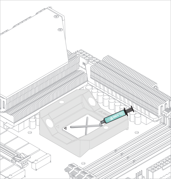

Refer here to learn more about how to apply thermal pastes.
- Back Exhaust
- Back Intake
Select airflow direction

The fans can be rotated to aid cable management

The fans can be rotated to aid cable management
- CPU_FAN
- CPU_FAN + CPU_OPT
Select your CPU fan header configuration


To get the best out of your cooler, it is recommended to adjust the fan speed control in the BIOS, follow this guide to adjust your PWM.


To get the best out of your cooler, it is recommended to adjust the fan speed control in the BIOS, follow this guide to adjust your PWM.