- AMD – SP3, TR4, sTRX4, sWRX8, SP6, sTR5
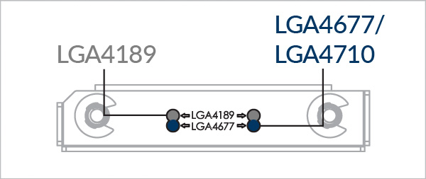
- Intel - LGA4710, LGA4677, LGA4189
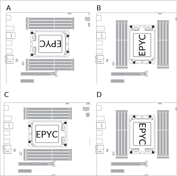
Выберите разъем процессора
Необходимые инструменты
 Отвертка с крестообразной головкой PH2
 Внимание
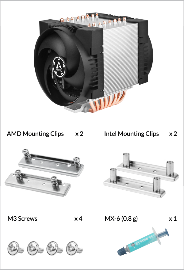
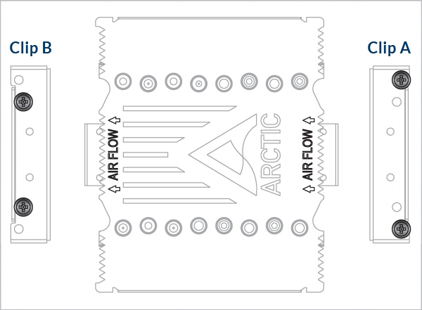
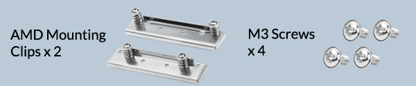
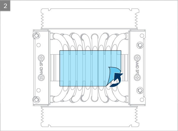
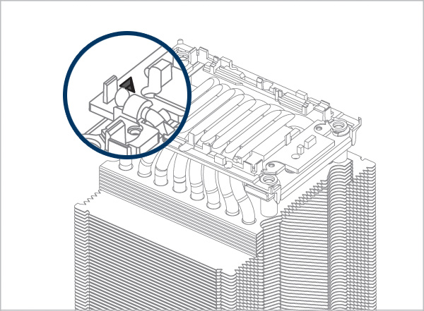
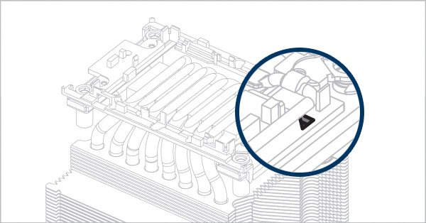
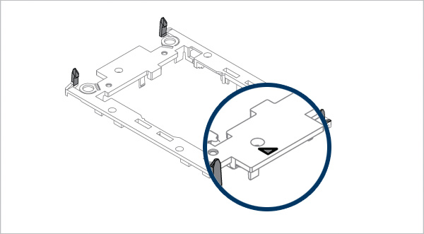
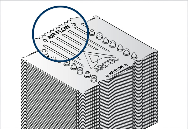
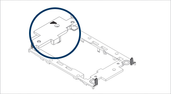
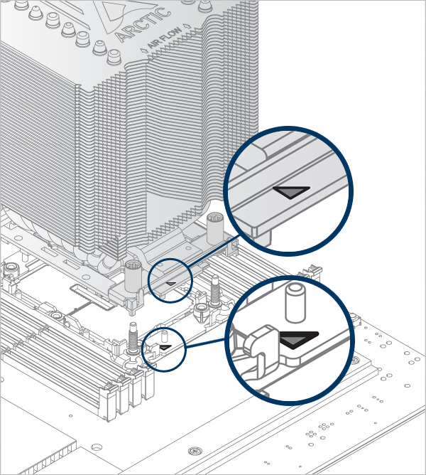
Обратите внимание: монтажные клипсы AMD асимметричны. Убедитесь, что вы правильно установили клипсы, следуя приведенной ниже инструкции.
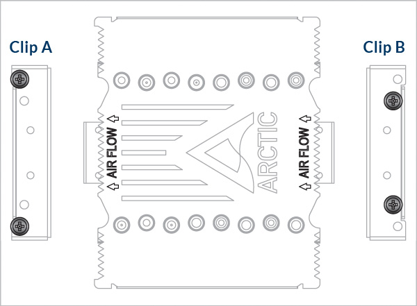
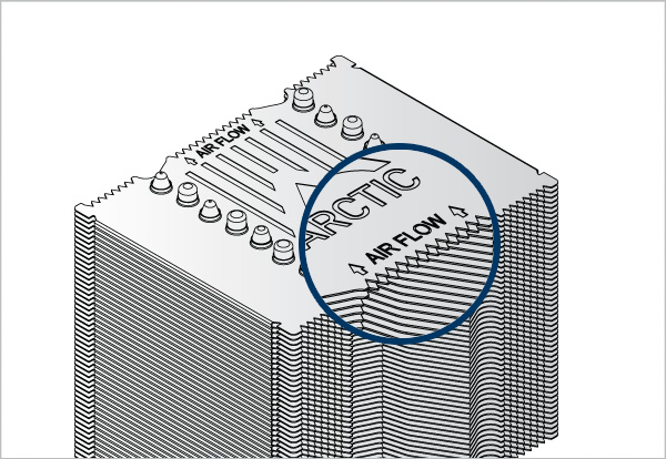
Расположите зажим A по стрелке выходного воздушного потока, а зажим B - по стрелке входного воздушного потока.

Внимание
Обратите внимание: монтажные клипсы AMD асимметричны. Убедитесь, что вы правильно установили клипсы, следуя приведенной ниже инструкции.

Расположите зажим A по стрелке выходного воздушного потока, а зажим B - по стрелке входного воздушного потока.


Внимание
Обратите внимание: монтажные клипсы AMD асимметричны. Убедитесь, что вы правильно установили клипсы, следуя приведенной ниже инструкции.

Направьте зажим A по стрелке впускного потока воздуха, а зажим B - по стрелке выпускного потока воздуха.


Внимание
Обратите внимание: монтажные клипсы AMD асимметричны. Убедитесь, что вы правильно установили клипсы, следуя приведенной ниже инструкции.
Направьте зажим A по стрелке впускного потока воздуха, а зажим B - по стрелке выпускного потока воздуха.

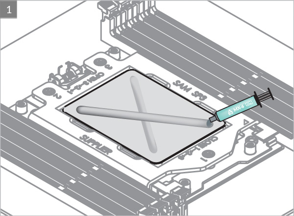

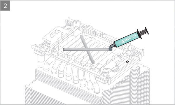
* Перейдите по этой ссылке, чтобы узнать больше о том, как правильно наносить термопасты.
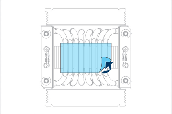
Установите нагнетающий вентилятор на входной стороне радиатора
Установите вытяжной вентилятор на выходной стороне радиатора
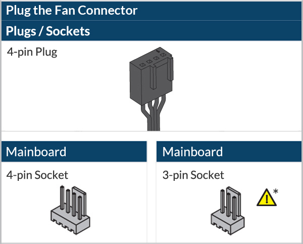
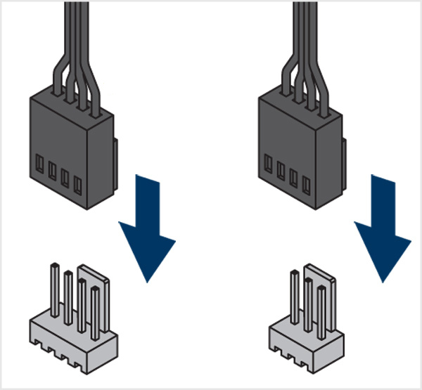
* Могут появиться некоторые механические помехи в окружающих компонентах. Вентилятор не будет контролироваться ШИМ.


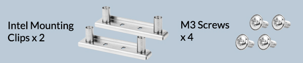
Необходимые инструменты

Внимание
Крепежные клипсы Intel имеют два набора монтажных отверстий. Убедитесь, что выбраны правильные крепежные отверстия для вашего сокета.


Внимание
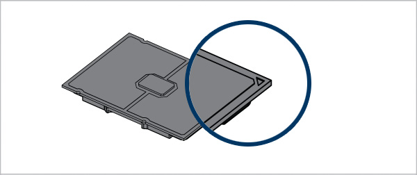
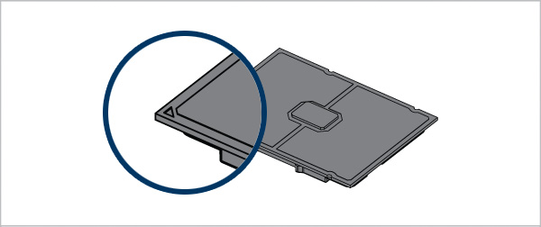
Please be careful when removing the dust cover and check the socket orientation. Look at the socket closely and see if the pins are intact. A damaged socket may prevent the system from booting.
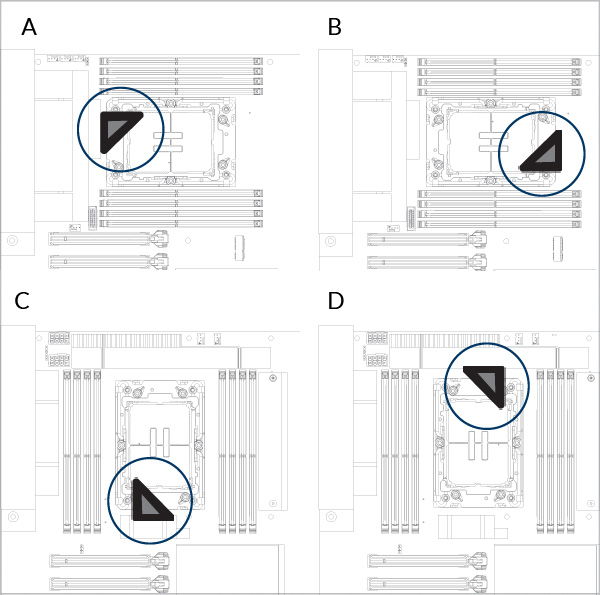
Проверьте ориентацию сокета
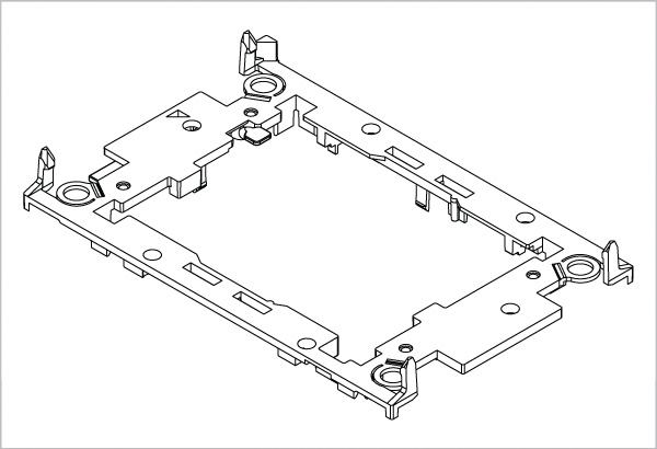
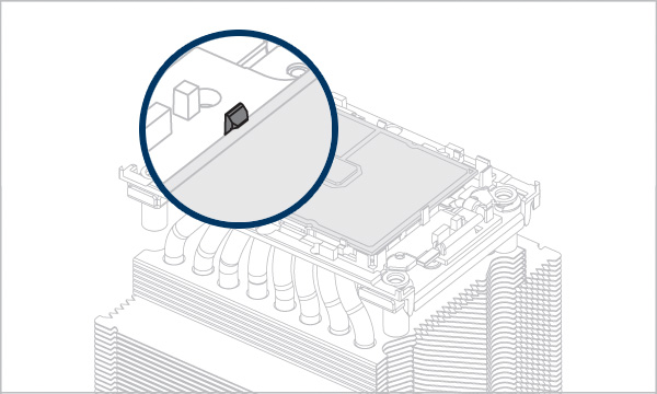
Обратите внимание, что для установки процессора LGA4189/ LGA4677 и радиатора требуется пластиковый держатель процессора, такой как показан выше. Эти держатели входят в комплект поставки розничных процессоров или материнских плат, а для процессоров с лотком их можно приобрести отдельно через торговых партнеров Intel.
Обратитесь в службу поддержки ARCTIC, если держатель для процессора LGA4189 недоступен для вашей версии продукта.


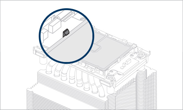
Совместите маркировку Pin1 на корпусе процессора со стрелкой выхода воздушного потока на радиаторе
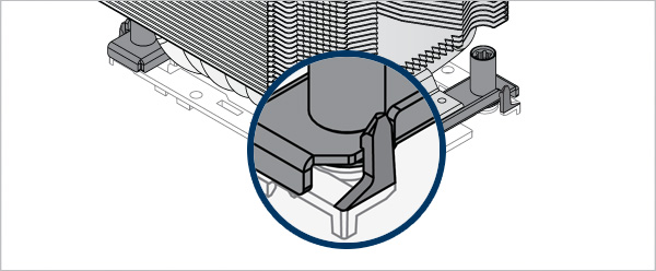
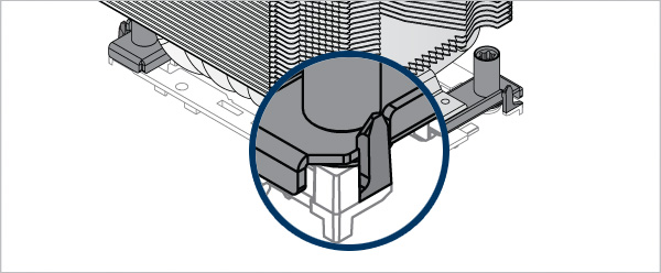
Убедитесь, что все фиксирующие выступы правильно прикреплены к радиатору


Совместите маркировку Pin1 на держателе процессора с маркировкой Pin1 на процессоре

Убедитесь, что все фиксирующие выступы правильно прикреплены к процессору.
Внимание
Незафиксированные стопорные язычки могут уронить процессор и повредить его или материнскую плату
Обратите внимание, что для установки процессора LGA4189/ LGA4677 и радиатора требуется пластиковый держатель процессора, такой как показан выше. Эти держатели входят в комплект поставки розничных процессоров или материнских плат, а для процессоров с лотком их можно приобрести отдельно через торговых партнеров Intel.
Обратитесь в службу поддержки ARCTIC, если держатель для процессора LGA4189 недоступен для вашей версии продукта.


Совместите метку Pin1 на корпусе процессора со стрелкой входного воздушного потока на радиаторе


Убедитесь, что все фиксирующие выступы правильно прикреплены к радиатору


Совместите маркировку Pin1 на держателе процессора с маркировкой Pin1 на процессоре


Убедитесь, что все фиксирующие выступы правильно прикреплены к процессору.
Внимание
Незафиксированные стопорные язычки могут уронить процессор и повредить его или материнскую плату
Обратите внимание, что для установки процессора LGA4189/ LGA4677 и радиатора требуется пластиковый держатель процессора, такой как показан выше. Эти держатели входят в комплект поставки розничных процессоров или материнских плат, а для процессоров с лотком их можно приобрести отдельно через торговых партнеров Intel.
Обратитесь в службу поддержки ARCTIC, если держатель для процессора LGA4189 недоступен для вашей версии продукта.
Совместите метку Pin1 на корпусе процессора со стрелкой входного воздушного потока на радиаторе
Убедитесь, что все фиксирующие выступы правильно прикреплены к радиатору


Совместите маркировку Pin1 на держателе процессора с маркировкой Pin1 на процессоре

Убедитесь, что все фиксирующие выступы правильно прикреплены к процессору.
Внимание
Незафиксированные стопорные язычки могут уронить процессор и повредить его или материнскую плату
Обратите внимание, что для установки процессора LGA4189/ LGA4677 и радиатора требуется пластиковый держатель процессора, такой как показан выше. Эти держатели входят в комплект поставки розничных процессоров или материнских плат, а для процессоров с лотком их можно приобрести отдельно через торговых партнеров Intel.
Обратитесь в службу поддержки ARCTIC, если держатель для процессора LGA4189 недоступен для вашей версии продукта.
Совместите маркировку Pin1 на корпусе процессора со стрелкой выхода воздушного потока на радиаторе


Убедитесь, что все фиксирующие выступы правильно прикреплены к радиатору


Совместите маркировку Pin1 на держателе процессора с маркировкой Pin1 на процессоре

Убедитесь, что все фиксирующие выступы правильно прикреплены к процессору.
Внимание
Незафиксированные стопорные язычки могут уронить процессор и повредить его или материнскую плату
Совместите маркировку Pin1 на корпусе процессора с маркировкой Pin1 на сокете
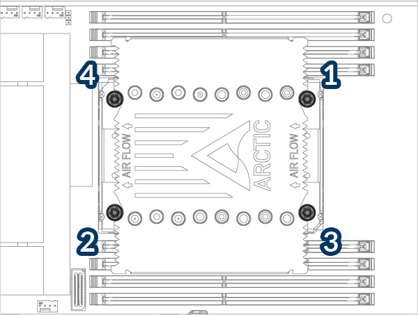
Соблюдайте порядок 1→2→3→4, 3 оборота на гайку.
Требуемый крутящий момент: 8 дюймов фунт-сила / 0,9 Н.м.
Установите нагнетающий вентилятор на входной стороне радиатора
Установите вытяжной вентилятор на выходной стороне радиатора

* Могут появиться некоторые механические помехи в окружающих компонентах. Вентилятор не будет контролироваться ШИМ.

Для лучшей производительности охлаждения мы рекомендуем настроить скорость вращения вентилятора в BIOS. Следуйте этим инструкциям, чтобы оптимально настроить параметры ШИМ.
Рекомендуемые продукты


