- AMD – SP3, TR4, sTRX4, sWRX8, SP6, sTR5
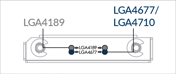
- Intel - LGA4710, LGA4677, LGA4189
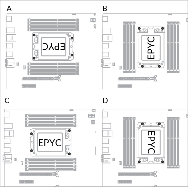
Scegliere il socket del processore
Utensili necessari
 PH2 Cacciavite a croce
 Attenzione
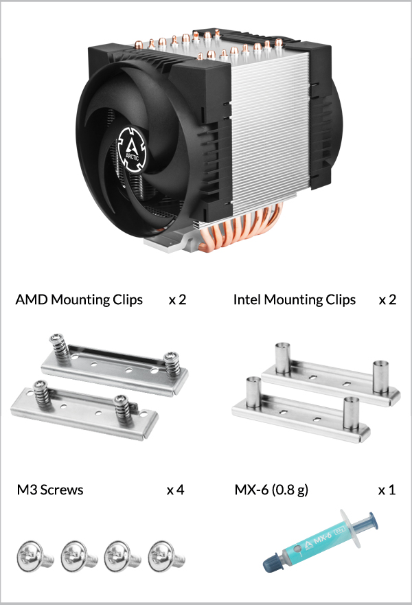
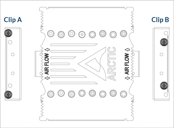
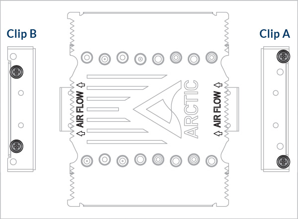
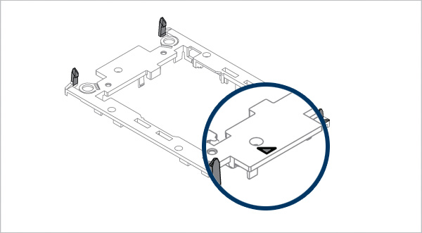
Nota bene: le clip di montaggio AMD sono asimmetriche. Assicurarsi di montare correttamente le clip seguendo le istruzioni riportate di seguito.

Allineare la clip A al lato dell'aria di scarico e la clip B al lato dell'aria di alimentazione.

Attenzione
Nota bene: le clip di montaggio AMD sono asimmetriche. Assicurarsi di montare correttamente le clip seguendo le istruzioni riportate di seguito.
Allineare la clip A al lato dell'aria di scarico e la clip B al lato dell'aria di alimentazione.


Attenzione
Nota bene: le clip di montaggio AMD sono asimmetriche. Assicurarsi di montare correttamente le clip seguendo le istruzioni riportate di seguito.

Allineare la clip A al lato dell'aria di scarico e la clip B al lato dell'aria di alimentazione.


Attenzione
Nota bene: le clip di montaggio AMD sono asimmetriche. Assicurarsi di montare correttamente le clip seguendo le istruzioni riportate di seguito.
Allineare la clip A al lato dell'aria di scarico e la clip B al lato dell'aria di alimentazione.


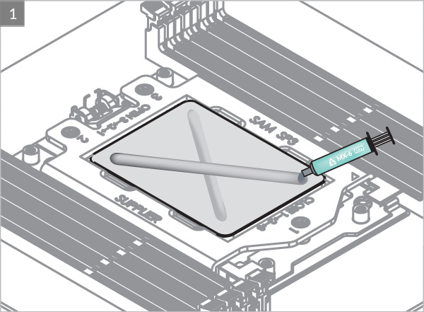

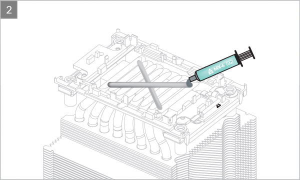
* Seguire questo link per saperne di più su come applicare correttamente le paste termiche.
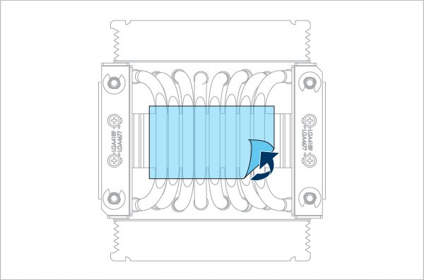
Installare la ventola push sul lato di ingresso del dissipatore di calore
Installare la ventola pull sul lato di uscita del dissipatore di calore
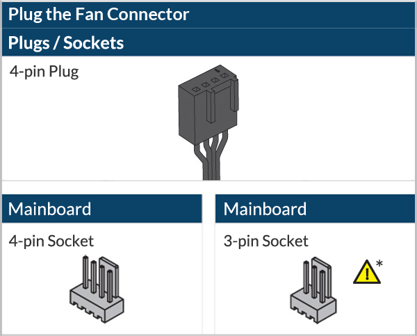
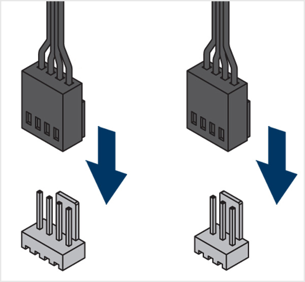
* Possono apparire alcune interferenze meccaniche con i componenti circostanti. La ventola non sarà controllabile tramite PWM.


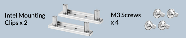
Utensili necessari
 Cacciavite Torx T30
Attenzione
Le clip di montaggio Intel hanno due serie di fori di montaggio. Assicurarsi di selezionare i fori di fissaggio corretti per il socket.


Attenzione
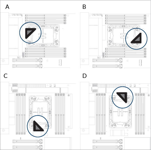
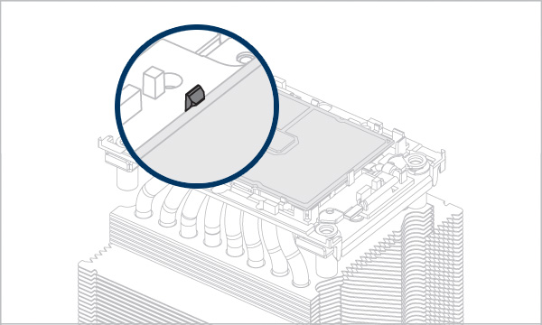
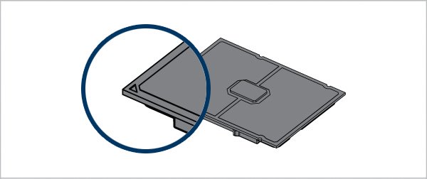
Prestare attenzione quando il coperchio antipolvere e si controlla l'orientamento della presa. Osservare attentamente il socket e verificare che i pin siano intatti. Un socket danneggiato può impedire l'avvio del sistema.
Controllare l'orientamento del socket
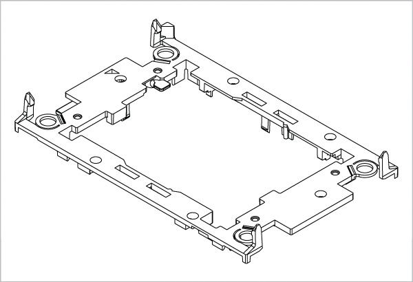
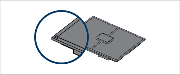
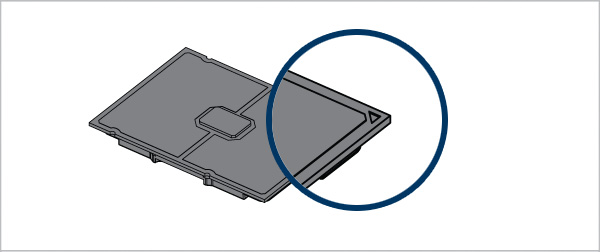
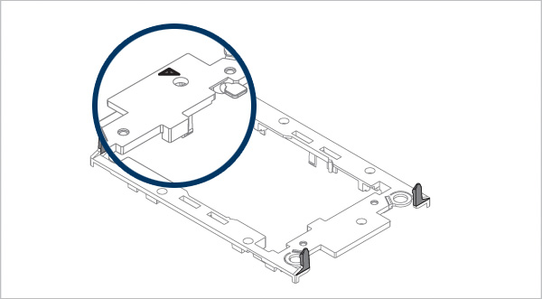
Si noti che l'installazione di un processore e di un dissipatore LGA4189/LGA4677 richiede un supporto per CPU in plastica come quello mostrato sopra. Questi supporti sono inclusi nella confezione delle CPU o della scheda madre e sono disponibili separatamente dai partner commerciali di Intel per le CPU di tipo tray.
Contattare l'assistenza ARCTIC se il supporto CPU LGA4189 non è disponibile per la versione del prodotto in uso.


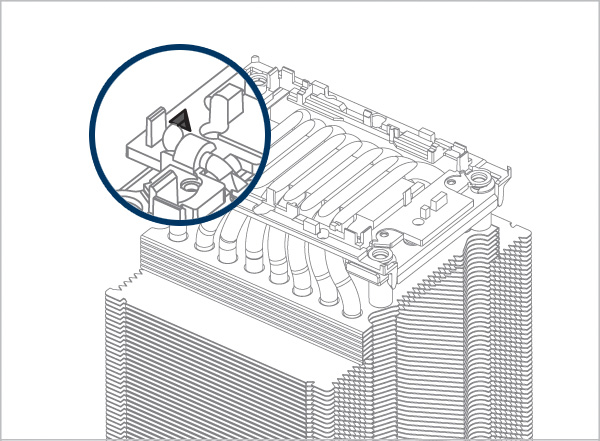
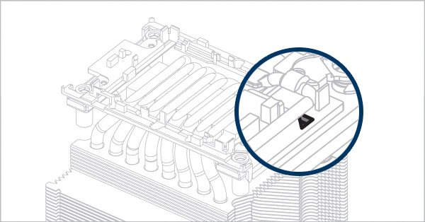
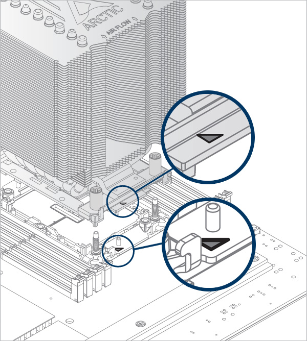
Allineare il segno Pin1 sul supporto della CPU alla freccia di uscita del flusso d'aria sul dissipatore
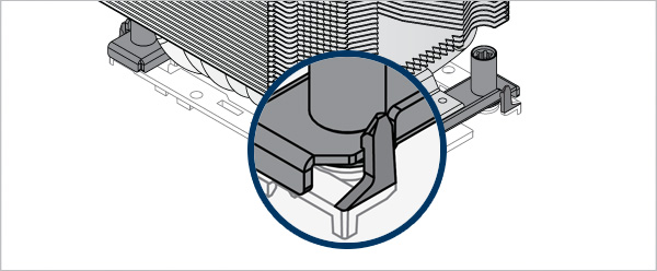
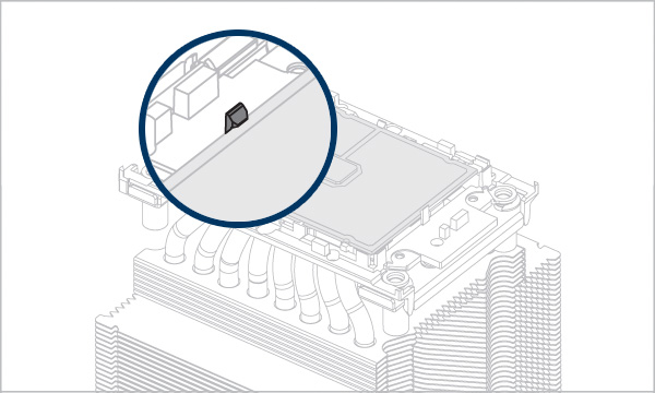
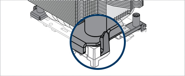
Assicurarsi che tutte le linguette di blocco siano fissate correttamente al dissipatore di calore


Allineare il contrassegno Pin1 sul supporto della CPU al contrassegno Pin1 sulla CPU

Assicurarsi che tutte le linguette di blocco siano fissate correttamente alla CPU.
Avvertenza
Le linguette di blocco non fissate possono far cadere la CPU e causare danni alla CPU o alla scheda madre
Si noti che l'installazione di un processore e di un dissipatore LGA4189/LGA4677 richiede un supporto per CPU in plastica come quello mostrato sopra. Questi supporti sono inclusi nella confezione delle CPU o della scheda madre e sono disponibili separatamente dai partner commerciali di Intel per le CPU di tipo tray.
Contattare l'assistenza ARCTIC se il supporto CPU LGA4189 non è disponibile per la versione del prodotto in uso.


Allineare il segno Pin1 sul supporto della CPU alla freccia del flusso d'aria in ingresso sul dissipatore di calore


Assicurarsi che tutte le linguette di blocco siano fissate correttamente al dissipatore di calore


Allineare il contrassegno Pin1 sul supporto della CPU al contrassegno Pin1 sulla CPU


Assicurarsi che tutte le linguette di blocco siano fissate correttamente alla CPU.
Avvertenza
Le linguette di blocco non fissate possono far cadere la CPU e causare danni alla CPU o alla scheda madre
Si noti che l'installazione di un processore e di un dissipatore LGA4189/LGA4677 richiede un supporto per CPU in plastica come quello mostrato sopra. Questi supporti sono inclusi nella confezione delle CPU o della scheda madre e sono disponibili separatamente dai partner commerciali di Intel per le CPU di tipo tray.
Contattare l'assistenza ARCTIC se il supporto CPU LGA4189 non è disponibile per la versione del prodotto in uso.
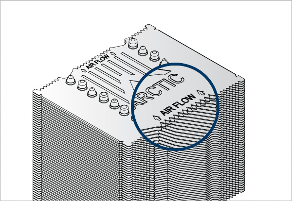
Allineare il segno Pin1 sul supporto della CPU alla freccia del flusso d'aria in ingresso sul dissipatore di calore
Assicurarsi che tutte le linguette di blocco siano fissate correttamente al dissipatore di calore


Allineare il contrassegno Pin1 sul supporto della CPU al contrassegno Pin1 sulla CPU

Assicurarsi che tutte le linguette di blocco siano fissate correttamente alla CPU.
Avvertenza
Le linguette di blocco non fissate possono far cadere la CPU e causare danni alla CPU o alla scheda madre
Si noti che l'installazione di un processore e di un dissipatore LGA4189/LGA4677 richiede un supporto per CPU in plastica come quello mostrato sopra. Questi supporti sono inclusi nella confezione delle CPU o della scheda madre e sono disponibili separatamente dai partner commerciali di Intel per le CPU di tipo tray.
Contattare l'assistenza ARCTIC se il supporto CPU LGA4189 non è disponibile per la versione del prodotto in uso.
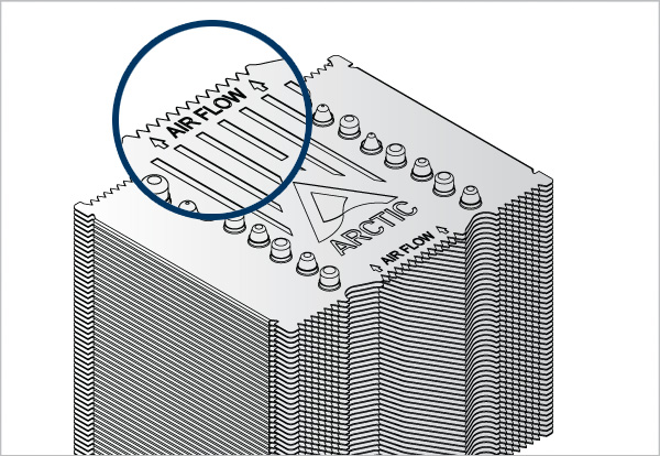
Allineare il segno Pin1 sul supporto della CPU alla freccia di uscita del flusso d'aria sul dissipatore


Assicurarsi che tutte le linguette di blocco siano fissate correttamente al dissipatore di calore


Allineare il contrassegno Pin1 sul supporto della CPU al contrassegno Pin1 sulla CPU

Assicurarsi che tutte le linguette di blocco siano fissate correttamente alla CPU.
Avvertenza
Le linguette di blocco non fissate possono far cadere la CPU e causare danni alla CPU o alla scheda madre
Allineare il contrassegno Pin1 sul supporto della CPU al contrassegno Pin1 sulla CPU
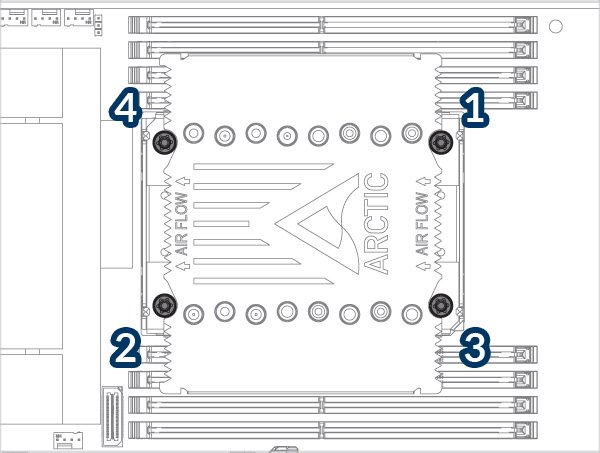
Seguire l'ordine 1→2→3→4, 3 giri per dado.
Coppia richiesta: 8 in.lbf / 0,9 N.m.
Installare la ventola push sul lato di ingresso del dissipatore di calore
Installare la ventola pull sul lato di uscita del dissipatore di calore

* Possono apparire alcune interferenze meccaniche con i componenti circostanti. La ventola non sarà controllabile tramite PWM.


Per le migliori prestazioni di raffreddamento, si consiglia di regolare la velocità della ventola nel bios. Segui queste istruzioni per regolare al meglio le impostazioni PWM.
Prodotti consigliati


