很遗憾,本文档暂无中文版本,以下为英文版本。
- AMD – AM5, AM4
- Intel – LGA1700
- Intel – LGA1851
Select your CPU Socket
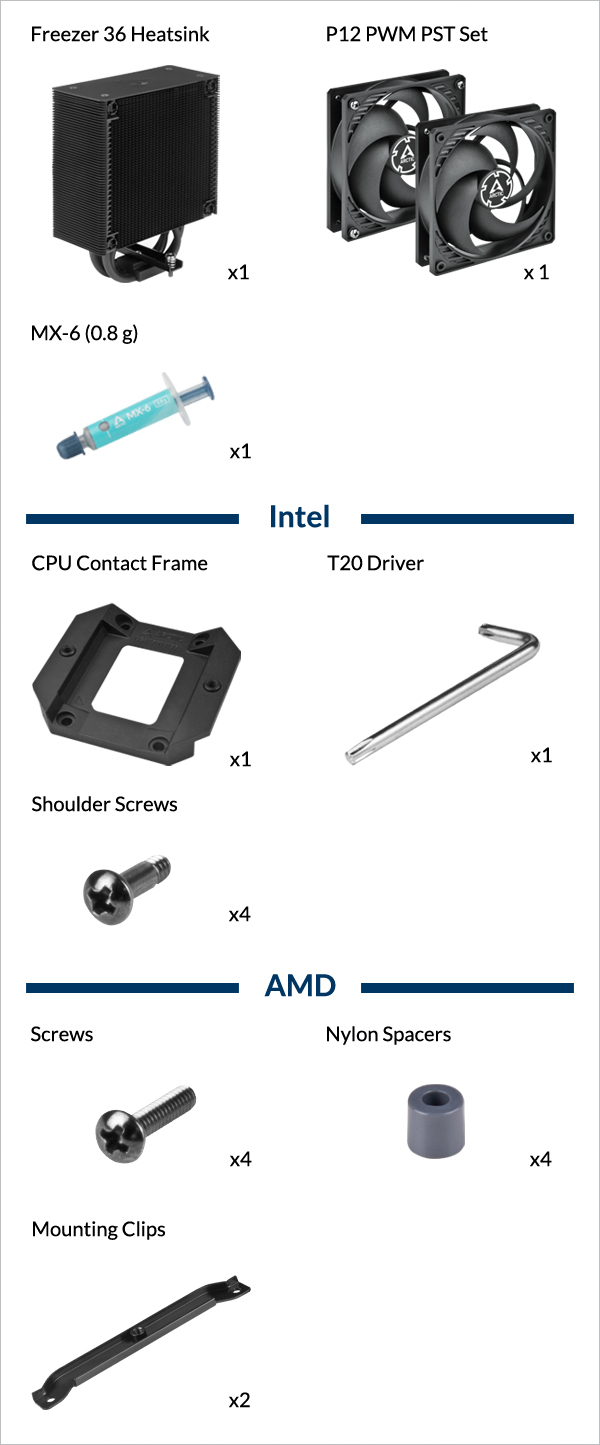
Required Tools
 PH2 Philips Head Screwdriver


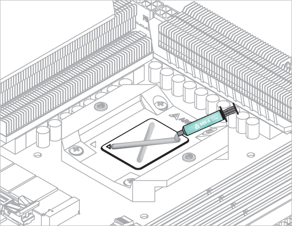
Refer here to learn more about how to apply thermal pastes.
- Back Exhaust
- Back Intake
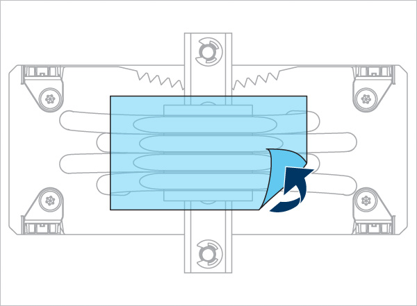
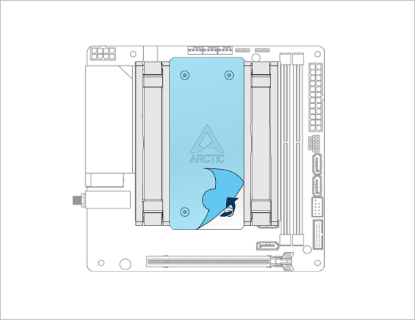
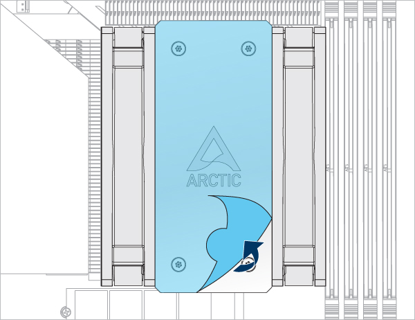
Select airflow direction
The fans can be rotated to aid cable management

The fans can be rotated to aid cable management
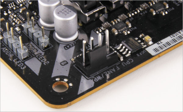
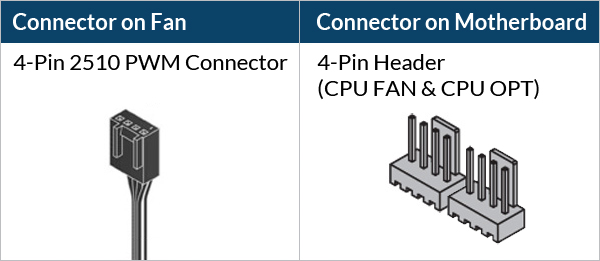
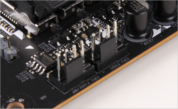
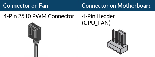
- CPU_FAN
- CPU_FAN + CPU_OPT
Select your CPU fan header configuration


To get the best out of your cooler, it is recommended to adjust the fan speed control in the BIOS, follow this guide to adjust your PWM.
To get the best out of your cooler, it is recommended to adjust the fan speed control in the BIOS, follow this guide to adjust your PWM.
Required Tools
PH2 Philips Head Screwdriver
 T20 Screwdriver (Included in packaging)
Attention
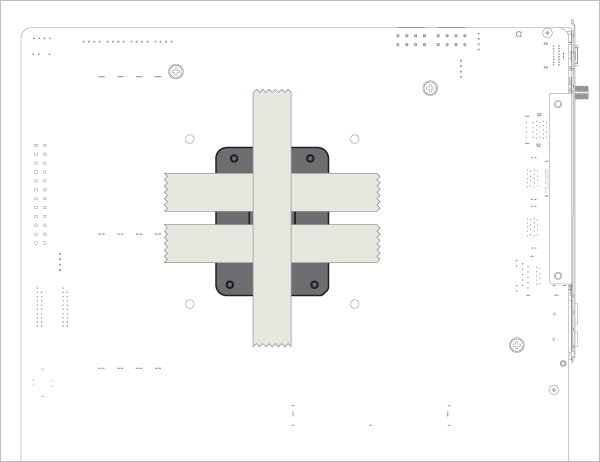
Secure the socket backplate in one of the 2 ways shown below depending on the status of your motherboard.
To support the socket backplate, place it on a flat, horizontal surface, like a thick padding (e.g., the packaging inner card)

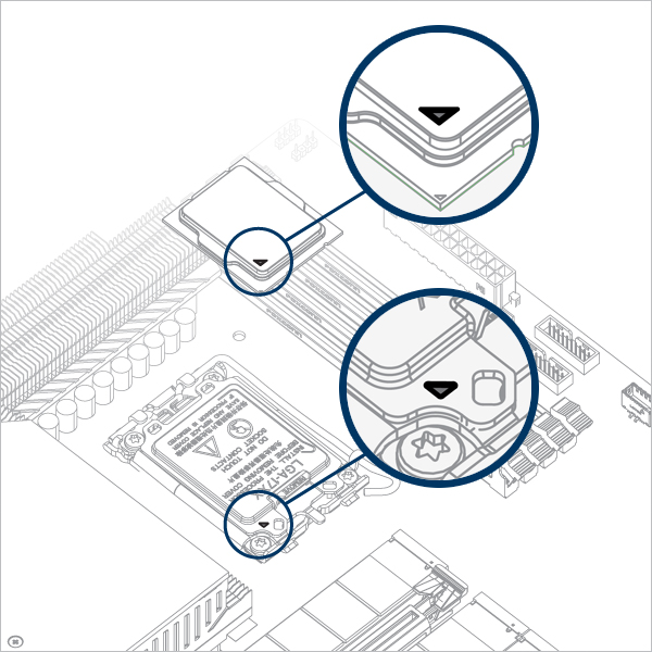
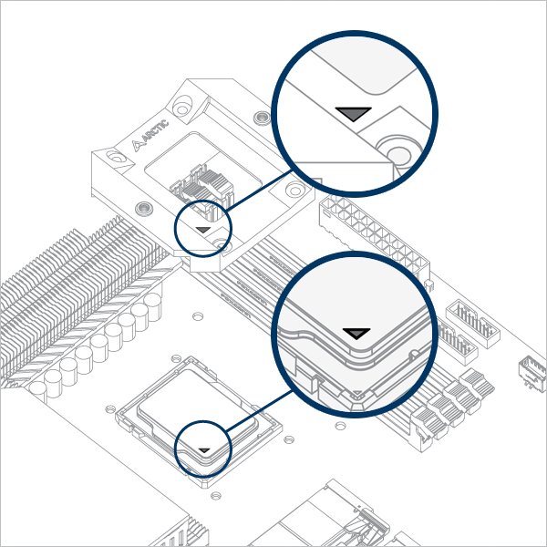
Open the Independent Loading Mechanism (ILM), align and place the CPU into the socket
Attention
Keep the removed parts for reassembly in the future. The ILM must be reinstalled if the motherboard is to be returned for service or warranty.

Attention
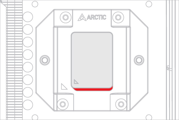
Align the CPU to the top edge of the cutout on the CPU Contact Frame, there should be a gap (highlighted in red) below the CPU.

Warning
Loosely engage all 4 screws by 2 turns before tightening them in a cross pattern evenly to avoid damaging the CPU.

The thick padding can be removed after the CPU Contact Frame is tightened.
Apply painter’s tape on the backside of the motherboard to secure the socket backplate. Lay the PC case flat on a horizontal surface.
Open the Independent Loading Mechanism (ILM), align and place the CPU into the socket
Attention
Keep the removed parts for reassembly in the future. The ILM must be reinstalled if the motherboard is to be returned for service or warranty.
Attention
Align the CPU to the top edge of the cutout on the CPU Contact Frame, there should be a gap (highlighted in red) below the CPU.
Warning
Loosely engage all 4 screws by 2 turns before tightening them in a cross pattern evenly to avoid damaging the CPU.
The painter’s tape applied to the backplate can be removed after the CPU Contact Frame is tightened.

Refer here to learn more about how to apply thermal pastes.

- Back Exhaust
- Back Intake
Select airflow direction
The fans can be rotated to aid cable management
The fans can be rotated to aid cable management
- CPU_FAN
- CPU_FAN + CPU_OPT
Select your CPU fan header configuration


To get the best out of your cooler, it is recommended to adjust the fan speed control in the BIOS, follow this guide to adjust your PWM.


To get the best out of your cooler, it is recommended to adjust the fan speed control in the BIOS, follow this guide to adjust your PWM.
Attention
Verify that your CPU Contact Frame is compatible with LGA1851.

Click below to see the detail views of all CPU Contact Frame variants.


Contact ARCTIC Support if you wish to obtain the LGA1851 compatible CCF.